INFLUENCE OF THE CATHODE SURFACE GEOMETRY
ON THE METAL PAD CURRENT DENSITY
Marc Dupuis1 and Valdis Bojarevics2
1 GéniSim Inc., 3111 Alger St., Jonquière, Québec, Canada G7S 2M9
marc.dupuis@genisim.com
2 University of Greenwich, School of Computing and Mathematics,
30 Park Row, London, SE10 9LS, UK
V.Bojarevics@gre.ac.uk
Keywords: Modeling, MHD, cell stability, irregular cathode surface, current density
Abstract
For the retrofit study presented in
[1] using the irregular top
surface cathode design presented in Figure 1, the cell voltage was
In the recent years, the Chinese aluminum industry has started to
reduced from 4.17 V to 3.85 V which is a reduction of 320 mV.
extensively use irregular top surface cathode blocks in its new cell
Out of that 320 mV reduction, 274 mV came from a reduction of
designs. The increase popularity of these new type of cell designs
the cell ACD (see Table 7 of [1]), clearly indicating that the new
in China is explained by the fact that they can be operated at a
cell design increased the cell stability as compared to the previous
much lower cell voltage.
one.
The cell voltage can be reduced because irregular top cathode
Yet, the cell stability analysis based on MHD-Valdis code
surface designs seem to increase the MHD cell stability which
presented in [4] predicted that adding such transversal ridges,
allows the cell to be operated at a reduced ACD. No satisfactory
while keeping the same metal level, hence, reducing the metal
explanation as to why the usage of irregular top cathode surface
volume, will decrease the cell stability. At best, if the metal
promotes MHD cell stability has been presented up to now.
volume is kept constant, the presence of those transversal ridges is
predicted to have a negligible impact on the cell stability.
The present work concentrates on the influence of the cathode
surface geometry on the metal pad current density as potential
The discrepancy between the cell stability analysis and the
observations was not addressed in [4]. It is important to notice that
cause of the change in the MHD cell stability behavior.
for standard flat top surface cathode design the MHD-Valdis code
was observed to be quite reliable in [5], so clearly, more research
Introduction
work was required.
A typical cell retrofit story involving the replacement of a
Study of the Impact of Cathode Surface Geometry on the
standard flat top surface cathode design by an irregular top surface
Cathode Surface Current Density
cathode design has been presented in [1]. Figure
1 below, a
reproduction of Figure 5 presented in [1], is showing an example
The local variation of the thickness of carbon above the collector
of geometry of the irregular cathode block surface. This is not the
bar(s) has, among other parameters, an impact on the current
only design used, since references
[2,
3] present alternative
density field on the cathode surface and hence the current density
irregular top surface cathode designs.
field in the metal pad. This effect was recognized as a key to the
prediction of the acceleration of the erosion rate of the cathode
reported in [6].
Yet this effect was not considered when the option to define the
geometry of the top cathode was added to the MHD-Valdis code
in order to produce the cell stability analysis presented in [7]. This
was the case simply because the deformation of the top cathode
surface like the one presented in Figure 2 (Figure 8 of [7]), was
caused by the global deformation of the cell. Obviously, as can be
seen in Figure 3 (Figure 9 of [8]), the global deformation of the
cell due to the cathode panel swelling do affect the geometry of
the cathode surface but is not affecting the thickness of the carbon
above the collector bar(s), and hence is not affecting the current
density field on the top cathode surface.
Since the usage of an irregular top surface cathode design do
affect the local variation of the thickness of carbon above the
collector bar(s), this variation must be considered in the
calculation of the cathode surface current density. Since no study
Figure 1. Example of irregular top surface cathode design
has been presented yet on that specific subject, this section is
presenting the result of such a study using a full cell side slice
thermo-electric 300 kA cell model.
Since the cathode carbon material is far more resistive than the
metal, the current has no incentive to enter into those ridges in
order to reach the collector bar. This is indeed what the full cell
side slice thermo-electric model solution is indicating. See Figure
5 for the cathode top surface current density solution.
Figure 2. Metal pad bottom profile input for an impact of
cell deformation cell stability study
Figure 5. Current density in the cathode block in A/m2
The resulting current density in the metal pad is presented in
Total displacement (m)
Figure
6, this time using a vector representation in order to
distinguish between the horizontal and vertical components of the
Figure 3. Cathode panel displacement results from thermo-
current density.
mechanical potshell and lining modeling
Study of the Impact of Longitudinal Ridges
Figure
4 presents the first model geometry case with four
longitudinal ridges. This is similar to the geometry presented in
Figure 5 of [2].
Figure 6. Current density in the metal pad in A/m2
As it is the horizontal component of the current density that is
promoting cell instability, it is pertinent to compare the horizontal
current density in the middle of the metal pad with and without
those four longitudinal ridges (keeping the same metal level). As
can be seen in Figure 7, the four longitudinal ridges are adding
local gradient of current density as the current has to go around
those ridges in order to enter the cathode block in the lower flat
sections between them.
The next step would be to analyse the impact of that change on
Figure 4. Full cell side slice thermo-electric model geometry
the cell stability by using a cell stability analysis code like MHD-
with four longitudinal ridges
Valdis, but unfortunately the required version of the code was still
under development when this study was carried out.
Figure 7. Comparison of the current density in the metal pad,
with and without ridges, in A/m2
Study of the Impact of Transversal Ridges
Figure 9. Current density in the cathode block in A/m2
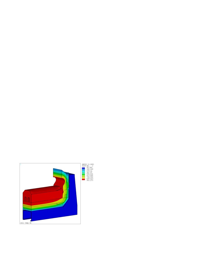
The second case studied is the case of the addition of transversal
ridges like the ones presented in Figure 4 of [2]. Figure 8 presents
the model temperature solution with the transversal ridge. That
geometry is not that different from the geometry presented in
Figure 1.
Figure 10. Current density in the metal pad in A/m2
Study of the Impact of Cathode Surface Geometry on the Cell
Stability
Figure 8. Full cell side slice thermo-electric model thermal
solution with a transversal ridge
500 kA Flat Cathode Surface Base Case Model
The base case of that cell stability comparison study is the 500 kA
Figure 9 shows that, as for the previous case, the cathode top
cell design presented in Figure
1 of
[9]. The
“classical”
surface current density is quite affected by the presence of the
asymmetric busbar layout is presented in Figure 11.
ridge.
The current density on the top surface of the cathode and at the
Figure 10 shows the resulting current density in the metal pad.
middle of the metal pad is presented in Figure 12. Since the
This time the ridge introduces a horizontal current density
component in the third dimension (the X direction in the model).
busbar network is perfectly balanced and the ledge toe position
has been optimized, there is essentially no horizontal current in
Again, the next step is to analyse the impact of that change on the
the longitudinal direction (JX) in the solution.
cell stability by using a cell stability analysis code like MHD-
Valdis, and again required version of the code was still under
Since the magnitude of the vertical component of the magnetic
development at the time this study was carried out.
field (BZ) is key to the cell stability, that solution is presented in
But for this very specific case, the flexibility of the available code
Figure 13. Finally the evolution of the interface position during
is permitting the user to build and hence analyse this case. That
the transient analysis is presented in Figure 14, from which that
work is presented in the next section.
cell design is predicted to be stable.
500 kA with Transversal Ridges Case Model
As in the previous study [4], the geometry of the top cathode
surface must be entered in MHD-Valdis’ BOTTOM input file.
This ensures that the code will account for that geometry in the
calculation of the metal pad current density and the subsequent
CFD solution of the metal flow.
But in the available version at the time of this study, this doesn’t
ensure that the geometry of the top cathode surface is affecting the
current density on that top cathode surface. Fortunately, in that
specific case, it is possible to ensure that by taking advantage of
the code user input flexibility.
The procedure to follow to achieve that is:
1.
Replace each double bars block in the model by 3
single bar block
2.
Change the flex to network busbar connections
Figure 11. Geometry of the 500 kA base case model showing
accordingly in MHD-Valdis’ BUSNET input file
the current intensity solution in each conductor in A
3.
Manually disconnect all the flexes of the middle block,
(so block 2,5,8 etc) in MHD-Valdis’ BARSIN input file
4.
Run MHD-Valdis with the option to use input from
BARSIN activated
Figure 15 presents the cell geometry obtained by following this
procedure. Figure
16 presents the current density solution
obtained following this cell geometry setup. This solution is only
an approximation of the correct solution as no current at all can
enter in the ridges.
Figure
17 presents the resulting magnetic field that is also
affected. Finally, Figure 18 presents the resulting transient cell
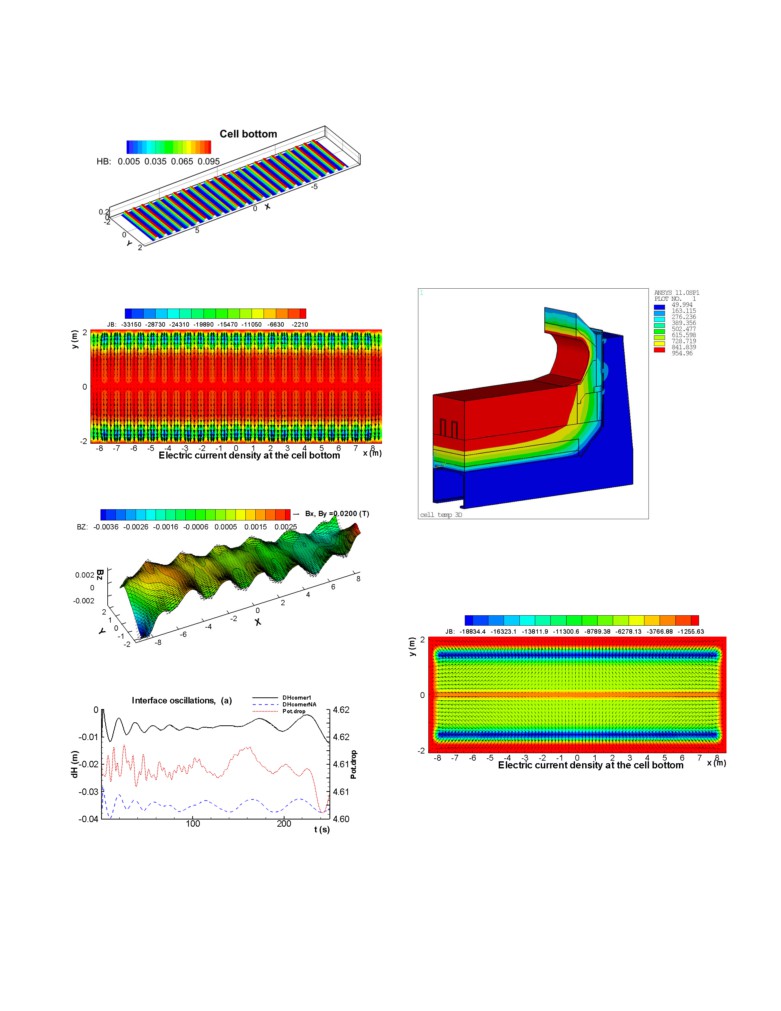
Figure 12. Current density solution on the top surface of the
stability results using the same metal pad depth and the same
cathode in A/m2
ledge toe position.
As for the cell stability study presented in
[4], the cell with
transverse ridges is predicted to be less stable than the base case
cell with flat bottom when keeping the same metal depth, hence,
decreasing the metal volume.
Figure 13. Vertical component of the magnetic field solution
in the middle of the metal pad in T
Figure 15a. Geometry of the 500 kA with transversal ridges
case model (BARSIN and BUSNET files)
Figure 14. Evolution of the interface position (m)
transversal ridges on the cell stability and that effect is negative or
in the best case, where the metal volume is conserved [4], neutral,
something else must be responsible for the observed gain of cell
stability.
In Figure 19 (Figure 4 of [1]), it can be seen that before the
retrofit, the ledge toe is extending a lot on the flat cathode surface.
This is no longer the case in Figure 1 after the retrofit. It is well
known that ledge toe extension under the anode shadow is bad for
the cell stability. In order to illustrate that, the base case flat
cathode surface model will be rerun this time to more accurately
represent the conditions of operation of cells in China before the
retrofit.
Figure 15b. Geometry of the 500 kA with transversal ridges
case model (BOTTOM file)
Figure 16. Current density solution on the top surface of the
cathode in A/m2
Figure 19. Typical ledge toe extension in cells prior to retrofitted
cathode with ridges in China
Compared to the base case model, this case has 5 cm less metal
and about 20 cm more ledge toe extension. The resulting current
density solution is presented in Figure 20.
Figure 17. Vertical component of the magnetic field solution
in the middle of the metal pad in T
Figure 20. Current density solution on the top surface of the
cathode in A/m2
The excessive ledge toe extension introduces a lot of extra
Figure 18. Evolution of the interface position (m)
horizontal current particularly increasing the JX in the end of the
cell where none were present in the base case with optimum ledge
500 kA Base Case Model with Less Metal and More Ledge
toe position. Figure 21 presents the corresponding magnetic field
This leaves intact the discrepancy between the cell stability
solution. Finally, Figure 22 presents the obtained transient cell
analysis results and the observations in China. If this time, it is
stability results.
assumed that the model represents in totality the effect of adding
The cell stability analysis that was performed for a cell with
transversal ridges on its cathode surface taking into account the
two ways those ridges affect the metal pad current density. The
conclusion of the study is that those ridges decrease the cell
stability if the metal height is kept the same (less metal volume).
A new version of the program (see the accompanying paper in this
volume) not available when the present study was carried out is
accounting for the effect and is bringing very similar general
conclusions.
Figure 21. Vertical component of the magnetic field solution
in the middle of the metal pad in T
Since the new results confirm the results of the previous study [4],
the discrepancy between the cell stability analysis and the
observations still needed to be explained.
The last part of the paper addresses this by suggesting that it is the
improvement of the ledge toe position that improved the observed
cell stability not the impact of the ridges on the metal pad current
density or the metal pad flow pattern.
Figure 22. Evolution of the interface position (m)
References
In a short time after the beginning of the simulation, the bath-
1.
J. Zhou et al., “Depth Analysis and Potential Exploitation of
metal deforms and touches the anode, stopping the simulation so
Energy-Saving and Consumption-Reduction of Aluminum
that configuration is predicted to be unstable.
Reduction Pot,” TMS Light Metals, 2012, 601-606.
2.
N. Feng et al., “Research and Application of Energy Saving
Thus clearly, despite the fact that on their own, the introduction of
Technology for Aluminum Reduction in China,” TMS Light
ridges on the surface of the cathode has a negative or at best
Metals 2012, 563-568.
neutral impact on the cell stability, it appears that the
3.
N. Feng et al., “Energy Reduction Technology for Aluminum
improvement of the ledge toe position between Figure 19 and 1 is
Electrolysis: Choice of the Cell Voltage,” TMS Light Metals
the main reason responsible for the gain of cell stability observed
2013, 549-552.
in the industrial cells in China.
4.
V. Bojarevics, “MHD of Aluminium Cells with the Effect of
Channels and Cathode Perturbation Elements,” TMS Light
Conclusions
Metals 2013, 609-614.
5.
S. Ruan et al., “Production Application Study on Magneto-
In the first part of the paper, it was demonstrated that ridges on
Hydro-Dynamic Stability of a Large Prebaked Anode
cathode surface affect the top cathode surface current density.
Aluminim Reduction Cell,” TMS Light Metals 2013, 603-
This influences the metal pad current density in two ways, the first
607.
one by locally changing the depth of metal and the second way by
6.
M. Dupuis,
“Development of a
3D Transient Thermo-
affecting the top cathode surface current density.
Electric Cathode Panel Erosion Model of an Aluminum
Reduction Cell,” COM Light Metals 2000, 169-178.
Depth of the metal variation is taken into account in the available
7.
M. Dupuis, V. Bojarevics and D. Richard, “Impact of the
version of MHD-Valdis at the time this study was carried out by
Vertical Potshell Deformation on the MHD Cell Stability
providing the geometry of that top cathode surface in the
Behavior of a 500 kA Aluminum Electrolysis Cell,” TMS
BOTTOM input file.
Light Metals 2008, 409-412.
8.
M. Dupuis,
“Mathematical Modeling of Aluminum
Changed to the cathode surface current density is not
Reduction Cell Potshell Deformation,” TMS Light Metals
automatically taken into account in the available version of MHD-
2010, 417-422.
Valdis but for the specific case of transversal ridges, it has been
9.
M. Dupuis and V. Bojarevis, “Retrofit of a 500 kA cell
taken into account by performing the appropriate adjustments to
design into a 600 kA cell design,” ALUMINIUM, 87 (1/2),
the MHD-Valdis input files.
2011, 52-55.